
Render a building in 3D from OpenStreetMap data
Since quite some time I have an interest in GIS and rendering, and after experimenting with the two separately I decided to finally try and render geographical data from OpenStreetMap in 3D, focusing on a small scale never bigger than a city.
In this article I will go through the process of generating a triangle mesh from a building shape, rendering and exporting it in a format suitable for Blender or game engines like Godot. I’m not an expert in the field but I’m sure there are people out there facing the same issues that may enjoy reading this.
In general, I find the topic of GIS and 3D processing very stimulating since it combines computer science with geometry and algebra and in a sense to how humans perceive and describe the world.
Importing OSM data into PostGIS
The first step of the process is to have the OpenStreetMap data inside a PostGIS instance. This is not strictly necessary since libraries like osmnx can use APIs to fetch this data on the fly in a few lines of Python, but I enjoy having it available in a relational database because it allows a lot of flexibility when analyzing and processing it, since I can use SQL.
To do that I download extracts from Geofabrik, essentially protobuf files with the data for a single region, and import them using pgOSM Flex, a tool I already used in a 2D visualization project and to which I contributed a bit in the past.
Once the data is imported I can directly visualize it using QGIS
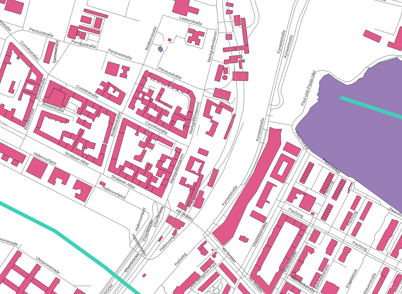
With QGIS it is possible to connect to PostGIS and explore the data in a few clicks
Since I’m using Python I can easily extract Shapely representations using Psycopg3 (in fact, I added that feature 😎). Asyncpg can do the same conversion transparently as well, but does not work well with Geopandas.
Shapely covers pretty much everything one may need regarding 2D geometry (geographical or not) and is quite memory-efficient so it’s a precious resource for this kind of project.
3D triangle meshes
Now that I have a Shapely object representing a feature like a building, I “only” need to transform it into a 3D shape. This can then be processed in 3D graphics software or game engines, displayed in the browser using WebGL (or WebGPU!) and rendered as an image.
There are a lot of techniques to represent 3D data and it would take another post, if you are curious have a look at the Open3D tutorial. For now let’s just say that for this use case there are two ways to do it:
- Voxels, can look cute, can be exported to Magica Voxels and Goxel, or adapted to 3D printing formats to create tactile maps of small areas. The simplicity of the representation enables a lot of operations with minimal effort.
- Triangle mesh, essentially what a game engine wants, very flexible and usually performant, can be tricky to process.
I ended up choosing the triangle mesh representation because with Open3D (or just some NumPy if we consider only surfaces) is easy to transform them into voxels, and the opposite is tricky.
Triangle mesh is only one way to represent meshes, but probably the one with best support in Python. In addition to Open3D the Trimesh library tries to be a “3D Shapely” to handle topologies in this format.
With this setup I started working on producing a 3D mesh from the Shapely object, using Trimesh and later on Open3D to render and voxelize it.
Export formats
An important feature I considered when looking for 3D libraries is the possibility to handle formats that can be used in other tools.
The situation is complicated, there are many competing formats, many are proprietary and/or badly documented. I ended up with two candidates: ply and glTF 2. Ply is interesting because it’s straightforward, simple enough that one can inspect the files by hand or generate them without external libraries. Being this simple it can be used in many softwares; a drawback is that it cannot contain fancy elements like animations or shaders or even textures (or better it does with extra attributes that are not fully standardized for what I can tell).
glTF 2 is a recent (2017) standard from the Khronos group, royalty free and documented, flexible and supported by most software. In the text form uses JSON which is easy to inspect. glTF is supported among others by Blender, Unreal, Unity and the Godot game engine. While I was working on this Godot released an alpha of the version 4.0 that crashed when importing a glTF mesh, I reported it and it was fixed in less than a day, really impressive.
glTF is also supported by Three.js and Babylon.js, which means not only that the resulting models can be visualized in the browser (a solution a lot easier to deploy across platforms) but there are several visualizers useful for 3d n00bs like me to debug the resulting model and troubleshoot the process.
Open3D
I’m using Python for this, for the simple reason it’s a language I know well and has a nice ecosystem of libraries to crunch numbers and process geometries. 3D rendering and games are not a typical use case for Python given its relatively low speed, but the success of the language for data analysis and machine learning still resulted in many libraries being developed to process LiDAR data or CT scans or perform tasks like segmentation and stereoscopy.
I ended up choosing Open3D because it seems very active, supports multiple representations and algorithms, has a decent documentation with examples and tutorials, can export in glTF and others in headless mode (e.g. from a web backend) with minimal setup and even render to static images which is useful for automated testing and troubleshooting, not to mention the possibility of creating videos or doing composition.
Trimesh caught my attention for its simplicity, being able to create meshes by specifying coordinates one by one can help in prototyping, in addition it offers many algorithms out of the box with reasonable dependencies and can be integrated with Open3D using glTF or directly passing around NumPy arrays.
The “holy” problem
Given a 2D building I want for a starter to generate a 3D prism. Using Trimesh this means to enumerate the 3D coordinates of the vertexes and then their indexes in tuples of 3 to specify all of the triangles.
This is probably one of the most common object type in a map, and one that can have a complex topology. Buildings can be concave and have holes.
So I started from this:
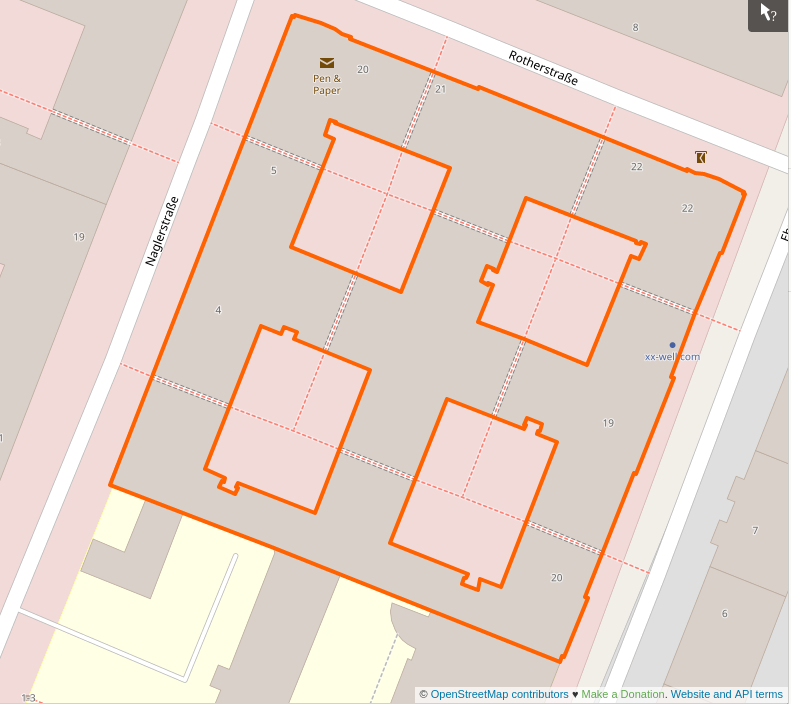
A real example of a building with holes
The fact the shape has holes (Euler number -6) and is concave means that to build it some triangles will have to be ignored because they end up being completely inside the volume, and reconstructing what’s the inside face (aka the normal) of each triangle is not simple.
A mesh can usually be rendered even when it’s geometrically wrong, but if it’s valid there are many interesting transformations than can be applied on top of it.
A mesh without holes is called watertight, and trimesh allows to easily check for this property with the is_watertight attribute. Notice that this has nothing to do with the topology of the mesh as a whole, a torus does for example have an Euler number of 0 (Trimesh shows it with the euler_number attribute) but if the mesh is defined properly it is watertight and there’s a defined inner and outer volume.
The broken building
The code for this is here: https://gist.github.com/jacopofar/5af606ccc4b39cee558060854f887262 to make it simpler the object it hardcoded as wkb, normally would be retrieved with many others from PostGIS to reproduce a whole area.
The first step is to transform the above shape, the building with 4 holes, in non-overlapping triangles. This is easily done by Shapely:
from shapely.ops import triangulate

...

with open("check_all_triangles.svg", "w") as fw:
    fw.write(shapely.geometry.MultiPolygon(triangulate(s))._repr_svg_())

The polygon above divided in triangles
Then it’s necessary to separate the triangle sides that are inside the polygon, using the within function:
mul_holes = shapely.geometry.MultiPolygon(
    [tri for tri in triangulate(s) if not tri.within(s)]
)
this is to generate a single MultiPolygon for display purposes, in the gist above you can see that the mesh creation does not need it.

The triangle sides not visible from the outside, to be ignored when generating the mesh

The outside triangle sides, used by the 3D mesh
You will notice that a side is missing from the inside segments. This will generate a problem later, and is a thing I didn’t notice in the first iteration of the code when this helpful image was not generated.
Now for each triangle I generate the two triangles on the mesh, for the two faces of the prism. Here I need to check that the triangle, not the single sides, is part of the shape.
for tri_num, tri in enumerate(internal_triangles):
    # it's 4 coordinates, the last is identical to the first to form a circuit
    for x, y in tri.exterior.coords[:-1]:
        vertices.append([x, y, 0.0])
    for x, y in tri.exterior.coords[:-1]:
        vertices.append([x, y, HEIGHT])
    # now 6 points have been added
    idx = tri_num * 6
    # bottom and top faces of the prism, use as is
    faces.append([idx, idx + 1, idx + 2])
    faces.append([idx + 3, idx + 4, idx + 5])
trimesh uses the indexes of the vertexes in the list to define a triangular face. I’m using lists for simplicity, but internally everything is based on Numpy and that’s the ideal format to use once the procedure is consolidated, it’s much more efficient especially when performing vector operations.
After defining the two faces (essentially the original 2D shape repeated at different heights) we need to do the lateral ones.
This is the logic to create them
for i1, i2 in ((0, 1), (1, 2), (2, 0)):
    if LineString([tri.exterior.coords[i1], tri.exterior.coords[i2]]).within(s):
        continue
    # add the two triangles making up the exterior face
    # there are 2 equivalent ways to split it, just use one
    faces.append([idx + i1, idx + i2, idx + i1 + 3])
    faces.append([idx + i1 + 3, idx + i2 + 3, idx + i2])
for each side of the triangle a LineString is created to check whether it is visible from the outside, and if it is two triangles are generated to form the rectangle connecting the top and bottom sides.
The (borked) result
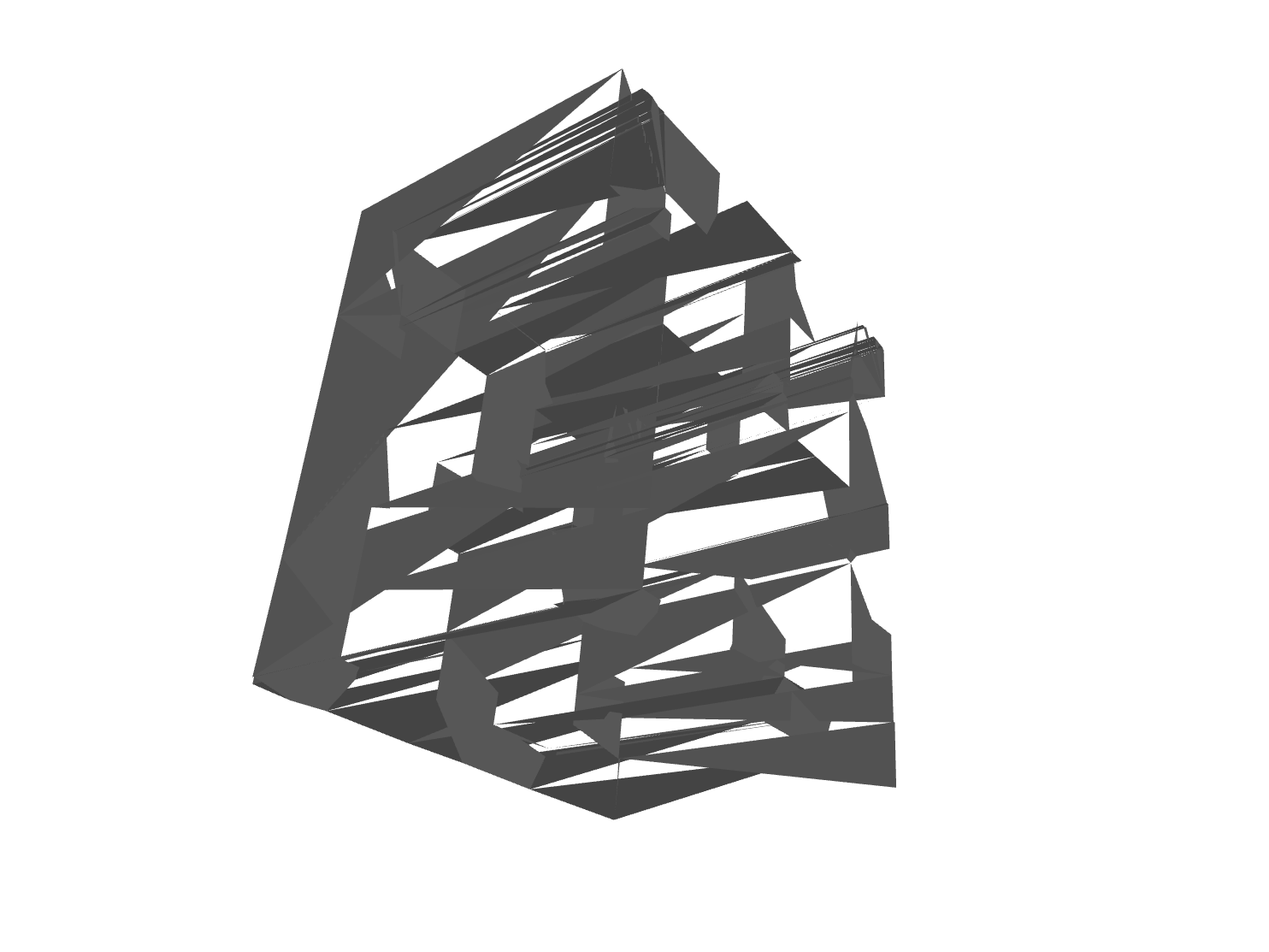
The mess resulting from the first version of the code. Rotating it makes it flicker
When the Pyglet render of the mesh materialized, I stared horrified at this mess. To be honest, I didn’t expect it to work already and was positively surprised the it had a vague resemblance with the intended shape.
Exporting the mesh in glTF to view it in various online visualizers confirmed that it was utterly broken. I tried to examine the issue by looking at the coordinates of the single elements and switching to a simpler shape, but it’s not exactly an easy task.
Web visualizers like the one above show that the wireframe is correct: the triangles are where they are supposed to be, there are no triangles within the volume or holes (well there’s one, but that’s a separate issue), but trimesh reports an Euler number close to -50 and the result is unusable!
I was close to abandon the project and make myself a Carbonara for consolation, when I observed a crucial detail: when rotating the solid each triangle appears or disappears depending on the side I’m observing.
The normals and winding order
This makes sense, up to some point. In 3D graphic there’s a concept known as normals. A normal is just a vector defining where the face is pointing, what side is the inside or outside one. When using Blender or high level libraries this is done automatically, although is mentioned in the famous Blender donut tutorial (that I highly recommend). I naively assumed normals were not important for such a simple mesh, and I was wrong. Inspecting the code of the library and doing some experiments I found that normals are defined by the order in which vertexes are defined (clockwise or counterclockwise). Geometrically, the triangle stays the same.
Trimesh offers helpers to recalculate the normals based on adjacent faces, but they are based on heuristics and produce a slightly less messy result, so it has to be fixed when producing the mesh in first place, that’s the only moment there’s a well defined inside and outside.
Sadly there’s not an universal standard used by all libraries, but OpenGL assumes that counterclockwise means front-facing.
Changing the order of the vertexes did produce a much better result.
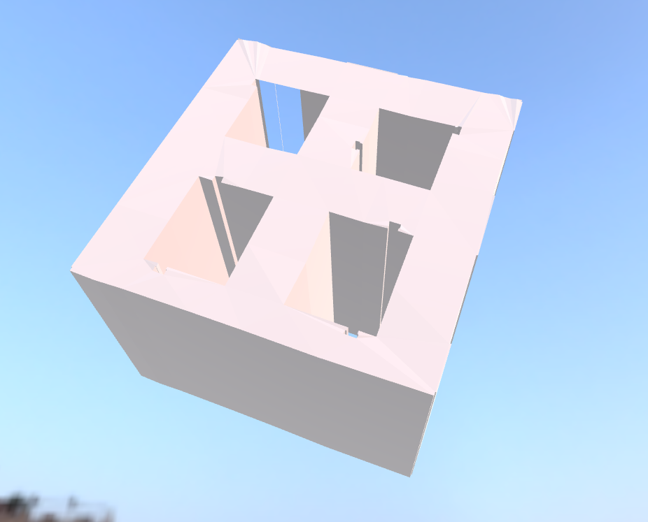
The mesh obtained after adjusting the vertex order to fix normals
The euler_number property is now a more realistic -9. Pyglet still flickers a bit when rendering it, but the browser visualizers are fine.
The missing side
Of course, there’s still a missing side. I initially thought it was an error with the normals, but the wireframe shows there’s no side at all.
This is because that side alone is, for some reason, failing the within check above, and is reported as an internal edge ¯\(ツ)/¯.
I didn’t investigate too much on this, it’s very possible that the 2D geometry is anomalous to begin with (in OSM I see an extra point in the polygon). My assumption is that if this happened with the first building-with-holes I took is probably very common.
Edit from 2024: this issue was due to the fact delaunay_triangles cannot be applied to concave shapes. For this use case one has to use, for example, the ear clipping method.
Back to voxel
These problems can be avoided with voxels because it’s trivial to use Shapely to detect when a “probe” coordinate falls within a complex shape or not, and in case of anomalous geometries the error is going to be nicer than this non-watertight mesh.
Another advantage of voxels is that an operation like producing the roof shape can be performed iteratively applying extrusion to a single slice of an element. Similarly, it’s easier to randomize elements.
This was the first step, after this basic rendering I’d have to handle colors, roof shape, level of detail and maybe, maybe, some animation. I decided to go back to voxels, because they are simpler to handle and can be transformed into stereolithographic models safely and consistently (voxelizing a mesh can produce artifacts). Additionally the navigation is simple (if one wants to show cars moving in the street for example).
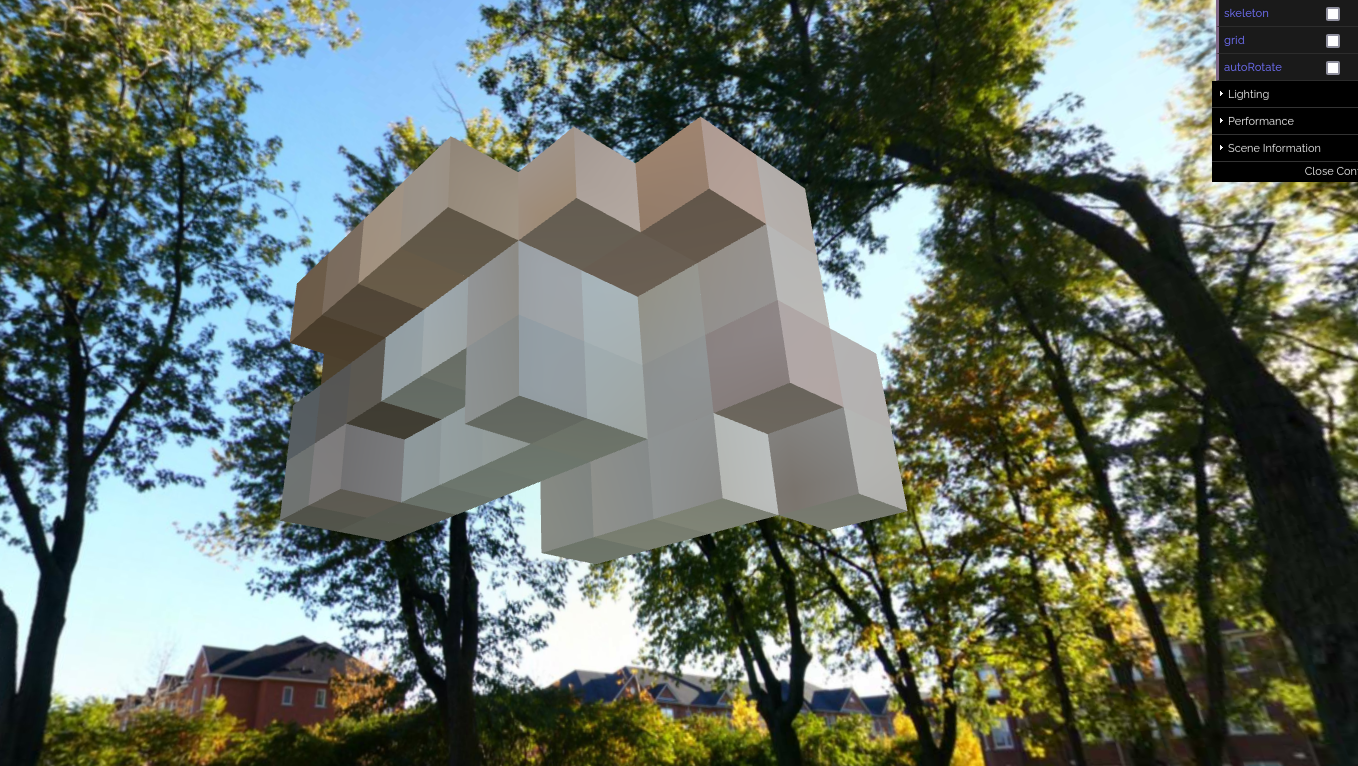
A voxel glTF mesh produced with Open3D (headless, running in Docker) and rendered in a browser